
A brief introduction
From Hand to Hightech
Imagine a sculptor shaping a complex sculpture from a raw marble block. They approach the material from different angles, alter the pitch of their tool, and work step by step towards the final form, always aiming to perfect the geometry and surface.
This very principle is transferred by 5-axis CNC milling into industrial manufacturing. It expands classic milling with additional degrees of freedom and enables the economical production of complex, precise components with significantly fewer clamping operations, shorter lead times, and high process reliability.
The Basics:
From Manual to CNC Milling
Milling is a subtractive manufacturing process in which a rotating tool removes material from a firmly clamped workpiece.
Traditionally, this processing takes place along three linear axes:
- X-axis: Move left and right.
- Y-axis Movement back and forth.
- Z-axis Movement up and down.
In normal circumstances, the achievable accuracy is approximately ±0.1 mm to ±0.05 mm (so one to two tenths of a millimeter). Very experienced skilled workers can possibly achieve ±0.02 mm achieve. With manual milling machines, quality and speed depend heavily on the operator. Each work step is performed, repeated, and checked individually. This makes the process flexible, but time-consuming and only limited in its reproducibility.
The abbreviation „CNC“ stands for „Computerized Numerical Control.“.
With the advent of CNC (Computerized Numerical Control) technology, machine movement became computer-controlled. The required processes are defined in the form of a program, typically written in G-code.1 This is used not only in machining but also in 3D printing, robotics, and other automated applications, and describes all movements, feeds, and process steps of the machine.
The decisive advance lies less in the maximum achievable accuracy and more in the Speed, repeatability, and process stabilityWhat used to have to be done step-by-step manually can now be programmed once and then repeated identically as often as desired, quickly, reliably, and always the same. Even standard CNC milling machines achieve process-reliable tolerances of ±0.02 mm to ±0.01 mm. High-precision machines, such as those used in tool and die making, even operate in the range of ±0.005 mm (5 micrometers) or better.
Milling Machines Compared (Manual vs. CNC)
| wdt_ID | wdt_created_by | wdt_created_at | wdt_last_edited_by | wdt_last_edited_at | Property | Manual milling machine | CNC milling machine |
|---|---|---|---|---|---|---|---|
| 1 | Typical accuracy | approx. 0.05 mm | approx. 0.01 mm | ||||
| 2 | Best accuracy | approx. 0.02 mm | < 0.005 mm | ||||
| 3 | Repeatability | Gering | Very high | ||||
| 4 | Limiting factor | Man & Machine | Machine & Process |
The Third Dimension
What is meant by 3D processing?
In machining, 3D machining generally describes the simultaneous operation of the three linear axes X, Y, and Z.This allows for the creation of complex freeform surfaces, such as those needed in mold or tool making.
The limitation lies in the tool orientation: The tool remains constantly aligned during machining. Angled drilling, undercuts, or multi-sided machining require additional setups or special fixtures and tools – involving higher time and cost expenditure.
3-axis milling machines accomplish exactly the scenario described. They produce freeform surfaces. These are complex, free-form surfaces.. However, the tool always remains in the same orientation to the workpiece, usually perpendicular from above.
The Fifth Dimension
5-axis CNC milling
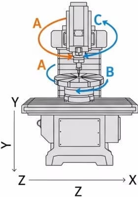
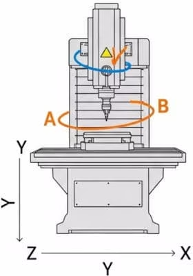
5-axis milling expands the three linear axes by two additional axes of rotation, with which the tool or workpiece can be swiveled:
- A-axis Rotation around the X-axis
- B-axis Rotation around the Y-axis
- C-axis Rotation around the Z-axis
A 5-axis machine combines three linear axes with two rotary axes. Depending on the machine concept, either the workpiece (e.g., via a swivel rotary table) or the tool (e.g., via a swivel head or trunnion head) is moved.
The crucial difference from 3-axis machining doesn't lie primarily in the complexity of movement, but in the additional freedom in tool setting.
Two modes of operation, one common goal
3+2 or simultaneous
With 5-axis milling, two basic types of machining are distinguished:
- 3+2-axis machining (indexing): The axes of rotation position the tool or workpiece at a fixed angle. The actual machining then takes place classically in 3 axes. This operating mode is widely used in industrial practice because it: A) enables multiple sides in a single clamping B) simplifies programming
- 5-Axis Simultaneous Machining (Simultaneous Milling): All five axes move simultaneously and interpolating. This machining method is primarily used for very complex free-form geometries where the tool angle needs to change continuously.
Important: The greatest economic benefit of 5-axis milling is often already achieved in 3+2 operation, as simultaneous milling increases programming effort.
Justified expense
Key advantages of a 5-axis CNC milling machine
The use of 5-axis technology offers clear advantages:
- Reduced setup times: Multi-sided machining in a single setup
- Higher precision: Fewer positional errors due to elimination of transformers
- Higher precisionEvery manual reclamping of a workpiece carries the risk of minor inaccuracies. These errors accumulate over multiple setups. Since the component is ideally clamped only once in 5-axis milling, these sources of error are eliminated. The relative accuracy of the machined surfaces to each other is significantly higher. This leads to an overall increased precision of the manufactured components.
- Better surface quality Shorter, stiffer tools and optimal rake angles
- Higher flexibility Angled holes, complex contours, undercuts, and variety of variants
This has a significant impact on quality and economic efficiency, especially with small and medium batch sizes and complex components.
Not automatically perfect
What is this type of machine not ideal for?
Despite its enormous advantages, a 5-axis milling machine is not always the best choice. There are applications in which it is uneconomical or technologically oversized.
- simple, prismatic serial parts
- very large, planar components with a focus on stability
- High-volume pure turned parts
This is in addition to higher investment, maintenance, and programming costs. The decision for 5 axes should therefore always technical and economic to be hit.
Simple, prismatic components in high quantities: For the production of large quantities of simple plates, blocks, or brackets that only have holes or pockets on one side, a 3-axis machine is often faster and more cost-effective. Setup time is less critical here than cycle time., and the complex movement capabilities of the 5-axis machine are not needed.
- Setup time in manufacturing occurs once per orderThe time a skilled worker needs to prepare the machine for a new order. This includes clamping the fixture, loading the CNC program, and inserting and measuring the tools.
- Cycle time in manufacturing repeats for each component in the orderThe time it takes for the machine to produce a single component. This includes loading the raw material, the actual milling process, and unloading the finished part.
For small quantities (e.g., 5 prototypes) is a long Setup time is the biggest cost factor. For large quantities (e.g., 10,000 series parts) is one Short cycle time is the key to profitability.

For components over 5 meters in size or with large surface areas, the focus is on stability and large travel paths. not on complex swiveling movements. For pure surface machining of large machine beds or base plates, special gantry or plano milling machines with 3 axes are often better suited.
Simple turned parts whose annual quantities start in the high four-figure range, Parts such as shafts, bolts, or flanges are primarily manufactured on lathes. Even though modern turn-mill centers have 5-axis capabilities, a classic lathe is the most economical solution for a pure turning part.
The acquisition, maintenance, and operating costs for 5-axis machines are significantly higher than for 3-axis centers. Programming is more complex and requires more expensive CAM software and highly qualified operators. Therefore, the decision for 5-axis machining must always be an economic one. Consequently, an economic comparison with alternative manufacturing processes always takes place.
Broadly positioned
What materials is the process suitable for?
Fundamentally, a CNC milling machine, regardless of the number of axes, can machine a wide range of materials. Suitability primarily depends on the machine's stability, spindle power, and the selection of the right tools and cutting parameters. 5-axis milling is used for machining practically all machinable materials., especially for difficult to machine and expensive materials.
- Steels and tool steelsFrom simple construction steels to case-hardening steels, to high-strength and hardened tool steels.
- Stainless steelsRust and acid-resistant steels (V2A, V4A), which are often used in the medical technology and food industries.
- Aluminum Alloys: Lightweight materials with outstanding strength-to-weight ratios, predestined for modern lightweight construction in the aviation and automotive sectors.
- Titanium Alloys Extremely high tensile, heat-resistant, and corrosion-resistant high-performance materials for safety-critical components in the aerospace and defense sectors.
- Plastics and fiber composites: A broad spectrum of technical thermoplastics (e.g., PEEK, POM) to highly rigid composite materials (CFRP/GFRP) for specialized, weight-optimized industrial applications.
Users benefit particularly from controlled tool guidance and more stable machining conditions when working with demanding materials.
The 5-Axis Advantage in detail
Challenge – Material SelectionSome materials are extremely hard (often > 58 HRC). The cutting pressure is enormously high, and conventional milling strategies quickly lead to tool breakage or poor surfaces. and feed rates can unleash their full potential here. Optimal tool positioning is a fundamental prerequisite for this.
- Stability is everything: Just like with Titan, the use short, massive tools a machining with the necessary stability to withstand high cutting pressure.
- HSC Strategies: Modern 5-axis strategies such as high-speed cutting (HSC) with small stepovers but extremely high rotational speeds
Challenge – Aluminum Alloys: A very common material due to its low weight and good machinability. Used in aircraft construction, motorsport, and mechanical engineering. The material is relatively easy to machine, so the challenge usually lies in the complex components. Machining „from the solid“ is common, requiring thin walls, webs, and bases, and we need to ensure efficient chip removal.
- Control over the delayBy completely machining the component in a single setup whenever possible, it is only „released“ at the very end. This minimizes warping during the process. Additionally, machining strategies can be chosen to remove material symmetrically, thereby relieving stresses in a controlled manner.
- Stable machining of thin walls: Through the optimal tool placement can the cutting pressure be ideally directed onto the labile wall instead of pushing it away. The use shorter, stiffer tools prevents vibrations and enables excellent surfaces, even with the most delicate structures.
- Perfect chip removal: By swiveling the component or the head, deep pockets can be positioned so that chips simply fall out due to gravity and coolant. This is often the decisive factor for being able to mill reliably at maximum speed (HSC – High Speed Cutting) at all.
Challenge – Titanium Alloys: These materials are extremely tough and conduct heat very poorly. During machining, enormous heat is generated, which does not dissipate into the component but concentrates in the tool. This leads to extremely rapid tool wear and can negatively alter the material structure of the workpiece (hardening). Difficult to machine, but indispensable in aerospace and medical technology due to their high strength, low weight, and excellent corrosion resistance.
- Less vibrationBy using shorter and thicker tools, the entire process becomes more stable and vibrations (so-called „chatter“) are minimized. This protects the cutting edge and improves surface quality.
- Better cutting conditionsBy constantly adjusting the angle of attack, the cutting force is optimally distributed and heat generation can be better controlled. This allows you to cut with the more robust flank of the tool instead of the sensitive tip., drastically increases tool life.
Challenge – SuperalloysNickel or cobalt-based alloys (e.g., Inconel) that are extremely heat-resistant and used in gas turbines or jet engines. These materials consist of fibers and a matrix (e.g., resin). During milling, they tend to delaminate (the layers separate), exhibit fiber pull-out, and rapid abrasive tool wear.
- 5-axis simultaneous machining is often the only way to produce the complex blade geometries here.
Challenge – Plastics and CompositesFrom high-performance plastics like PEEK or POM to fiber-reinforced materials such as CFRP (carbon fiber-reinforced plastic) or GFRP (glass fiber-reinforced plastic).
- The decisive advantage is the controlled tool setting. The tool can be tilted so that the fibers are cut cleanly and not torn out of the matrix. This is absolutely critical for component quality. A 3-axis milling machine that always comes from above would crush the upper layers and cause fraying.
Well-founded and implementable
A deeper insight into strategy and technique
The machine structure, also referred to as kinematics, is a key determinant of a 5-axis milling machine's precision, dynamics, and application scope.
Machine kinematics
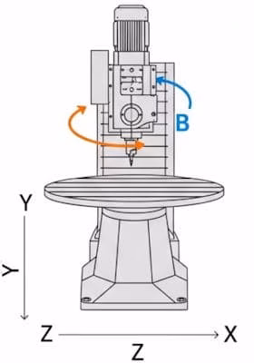
- Swivel Round Table: High stability and accuracy, especially suitable for small to medium-sized components
- Swivel or clevis: Suitable for large or heavy workpieces, as the workpiece remains firmly clamped and the movement is done by the tool.
Modern CNC controls ensure that the tool tip follows the programmed path exactly, even with swiveled axes. The use of Heidenhain controls with RTCP and TCPM continuously corrects the position of the tool tip.
Comparison of Machine Kinematics
 |
 |
 |
|
| Attribute | Table swivel turntable | Forkhead | Swivel head (or tilt/swivel head) |
| Moving component | Workpiece | Tool | Tool and workpiece |
| Axes of rotation | A and C axis (mostly) | A and B axes | B and C axes |
| Advantages | High stability, as the head remains stationary | Larger workspace, as the table does not swivel | Good compromise between stability and flexibility |
| Better workpiece accessibility | Ideal for large and bulky workpieces | Enables complex contours on large workpieces | |
| Well suited for heavy machining | More flexible tool swivel range | ||
| Disadvantages | Workspace restricted by table movement | Lower stability compared to the table tilting system | More complex control and kinematics |
| Dynamics for heavy workpieces are limited | Potential for collision due to the larger head | Possible restrictions in the range of motion | |
| Typical Applications | Small to medium, complex components (e.g., impellers, medical implants, mold making) | Very large components (e.g., in aircraft manufacturing or the energy sector) | Large yet complex parts that require high flexibility (e.g., in tool and mold making) |
Tool Center Point Control (TCPC) / Traore
Only with Siemens control units is the function called Transformation Orientation, Traori.
TCPC ensures that the tool tip travels exactly along the programmed path on the workpiece, even when the linear and rotary axes have to perform complex compensation movements. Without this function, precise programming and machining in 5-axis operation would be practically impossible. The controller compensates for the tool's length change and the movements of the rotary axes in real-time. A crucial function of the controller during simultaneous milling.
The programmer only tells the machine where the tool tip should be and how it should be oriented. The machine itself takes care of the complicated mathematics of how the axes need to move to achieve this.
CAM programming and postprocessor
The complexity of toolpaths in simultaneous milling absolutely requires the use of a powerful CAM (Computer-Aided Manufacturing) system. Programming is no longer done at the machine, but on the computer using a 3D model.. A critical component is the post-processor. It is the „translator software“ that converts the neutral toolpaths from the CAM system into the specific G-code of the respective machine controller. A perfectly adapted post-processor is the key to flawless and efficient manufacturing.
The process looks simplified like this:2
- Input (The „What“): An engineer designs a component in a CAD (Computer-Aided Design) program. The result is a digital 3D model.
- Processing (The „How“): This 3D file is loaded into the CAM software. Here, a programmer (often the CNC machinist themselves) no longer decides was is being built, but how it is being built. He determines:
- What tools are used? (e.g., „First a coarse roughing end mill, then a fine ball end mill.“)
- What strategy is driven? (e.g., „First empty the bags, then drive the contour, then set the holes.“)
- With which parameters? (e.g., speed, feed rate, depth of cut – the so-called cutting conditions).
- Output (The „Guide“): The CAM system calculates the exact tool paths from all these specifications. These paths are then used by a Postprocessor (a part of the CAM software) is translated into a specific machine code, usually G-code called.
- Result: This G-code is a long text file full of coordinates and commands (e.g.
G01 X100 Y50 Z-5 F2000which tells the CNC machine exactly how to move to manufacture the part.
Without CAM software, manufacturing complex parts, such as those produced by 5-axis milling, would be practically impossible.3
- Efficiency The software calculates the most efficient tool paths, optimizes cutting speeds, and minimizes idle travel, drastically reducing machining time (cycle time).
- Complexity: A person cannot manually program the thousands or millions of coordinate movements necessary for a fluid 3D surface (like that of a turbine or an ergonomic grip).
- Visualization & Simulation Modern CAM systems simulate the entire machining process beforehand on the screen. The operator can see how the tool removes material and, more importantly, whether it will Collision comes (e.g., whether the tool holder collides with the workpiece).
Since a standard post-processor is often not perfect, it is adapted to the specific needs and wishes of the company. An experienced CNC machinist or programmer adapts it so that it is perfectly matched to the specific machine and operational processes. This is necessary in order to all special functions of the machine how to use special measurement cycles, Internal company programming standards for more security to enforce and the Optimize NC code for maximum efficiency, by eliminating unnecessary movements and utilizing machine-inherent cycles.
Optimization of cutting conditions
The true art of 5-axis milling lies in the strategic use of the additional degree of freedom. Instead of „somehow“ machining a component, the programmer can continuously optimize the tool's orientation. For example, when finishing freeform surfaces, a ball or torus cutter can be oriented so that not the sensitive tip, but the more robust circumference of the tool does the cutting. This increases the effective cutting radius, which leads to a drastically improved surface finish with the same stepover. Defining the optimal cutting conditions (feed rate, spindle speed, depth of cut) is a highly complex task in the 5-axis context, requiring a great deal of experience.
Optimization of cutting conditions
| wdt_ID | wdt_created_by | wdt_created_at | wdt_last_edited_by | wdt_last_edited_at | Parameter will be increased | Effect on productivity | Impact on Surface Goods | Effect on tool wear |
|---|---|---|---|---|---|---|---|---|
| 1 | Rotational speed (n) | Climbs | Improves (to an optimum) | Rises sharply | ||||
| 2 | Feed (f) | Climbs | Worsening (grooving) | Rises moderately | ||||
| 3 | Cutting depth (ap/ae) | Rises sharply | Minor influence (can worsen with instability) | Rises moderately |
Key findings summarized
Conclusion and Outlook
5-axis milling is far more than just machining with additional axes.
It is a strategic tool for Reduction of clamping forces, to the Increasing process safety and to the economic production of complex components.
Not maximum complexity, but the targeted and practical use of the additional degrees of freedom determines success. With increasingly powerful CAM systems and CNC controls, 5-axis machining will become even more important.
- Rahul Awati for ComputerWeekly from August 20, 2024: G-Code Explained ↩
- Siemens.comComputer-aided design (CAD). Accessed November 3, 2025 ↩
- Autodesk.comCAM software for CNC Machining (eng) Accessed November 3, 2025 ↩


